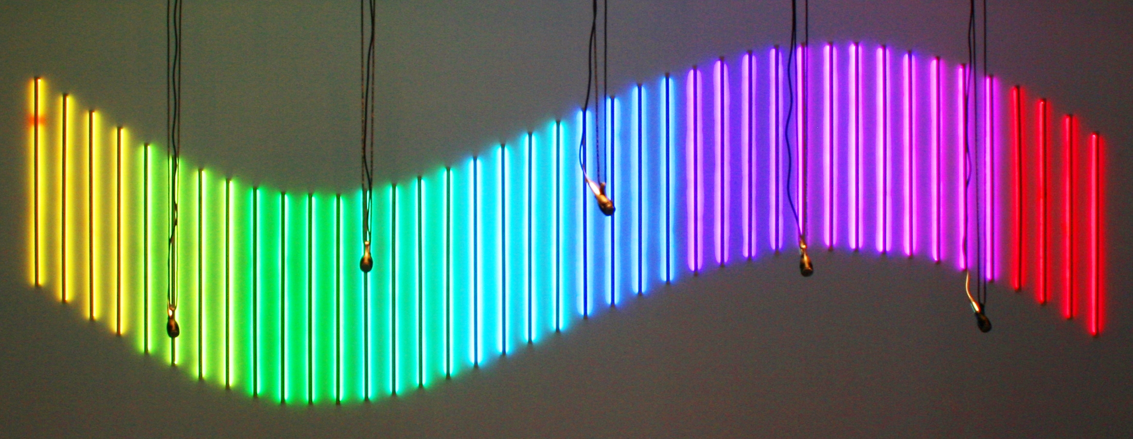
If you happen to have a few RGB LED strips around and you play with electronics you are probably tempted to hook them to your arduino (or other preferred microcontroller) and paint your favourite corner of the house with beautiful colours.

Now, if you are lucky and the LED strips have a common anode that's quite simple; follow the instructions that Ladyada has put together and you are done. However if the LED Strip happens to have a common cathod (i.e. red, greeen and blue share the negative side of the voltage gap) you need a bit more circuitry to control with your 5V arduino the oscillation of the +12 volts that led strips tipically require (a bit of further discussion on this arrangement is available).
Tu put it simply you need a low power transistor to provide a voltage high enough to toggle the power mosfet, as the 5V of the arduino are not enough; you can achieve this (for each signal) with a circuit like the following:

Well, in our case we wanted to power 10 such strips and control R, G and B of each one indipendently, so we needed 30 channels; the mosfet used in this configuration is quite overspecified but it has been selected to allow higher loads in the future, if needed, and they are only about 1 pound each anyway.
The next hurdle now is to be able to control the PWM of 30 channels without spending too much time in the design of the circtuitry. The easy way out I chose is to use SoftPWM, a library that allows you to control every I/O pin as a PWM output.
This means that an arduino can control up to 20 channels, so I have connected two arduinos through the I2C protocol to control the 30 channels. The I2C only uses two pins and leaves the Seial port free to communicate with the PC. Of course the PC is optional and the control logic can be stored int the arduino Master firmware. The lenght of the arduino chain is limited by the addresses available on the I2C bus and the desired refresh rate, but this is far from being a problem in this implementation. The overall framework looks like this:
In our case the hardware is controlled from a PC that is animating the space in an interactive installation, but I've also prepared a custom application to control the light effects that will soon be made availanble on our GitHub repository along with the EagleCad schematics and board drawings.

Find by timeline:
2024
March
January
2023
December
November
September
2022
December
November
July
June
2021
December
October
September
February
2020
November
October
2019
December
November
January
2018
December
November
October
June
March
2017
December
November
October
September
August
June
April
March
February
2016
November
September
July
June
April
January
2015
November
October
August
March
2014
December
October
September
August
July
June
May
March
January
2013
September
July
May
April
February
January
2012
December
October
September
August
July
June
May
April
March
February
January
2011
December
March
January
2010
December
October
September
June
May
Find by tag:
, activation, art, Art_and_science, art_festival, art_nstallation, Art_trail, Arte, Arte_e_Tecnologia, artista_della_luce, artisti, artists_studio, artists_talk, artivism, Audio Video Interaction, boats, Campaigns, code_art, conetemporary_art, Connect2, creative_software, designing_lights, digital_art, Events, exhibition, Exhibitions, floating_art, floating_installation, flotilla, Gloria, Gloria_Ronchi, hope, immersive_art, Installation, interaction_design, interactive, interactive_installation, interactive_public_art_installation, led, light, light_artwork, light_festival, light_installation, lightart, lighting, Links, lit, london, luce, luci, luci_artista, lumiere, media_architecture, media_art, open_studio, OpenSource, origami, origami_boats, paper_boats, Proposals, public, Public_art, public_sculptures, scultura_di_luce, software_art, studio_d_artista, water, winternights
Private:
Login

